Loading the cutaway. The original drawing is still available below.
Sibiu, Romania · Conrad Haas · sixteenth century
A three-stage rocket.
In an armourer’s
notebook.
In the sixteenth century, Conrad Haas drew rockets in stages. Historians explain how they fired in sequence. Look inside, then decide what stays on board.
↓ Scroll to look inside
In this story
The original drawing
Conrad Haas · 1529
View the document and attribution ↗
A handwritten date
1529. What does this number date? ↗
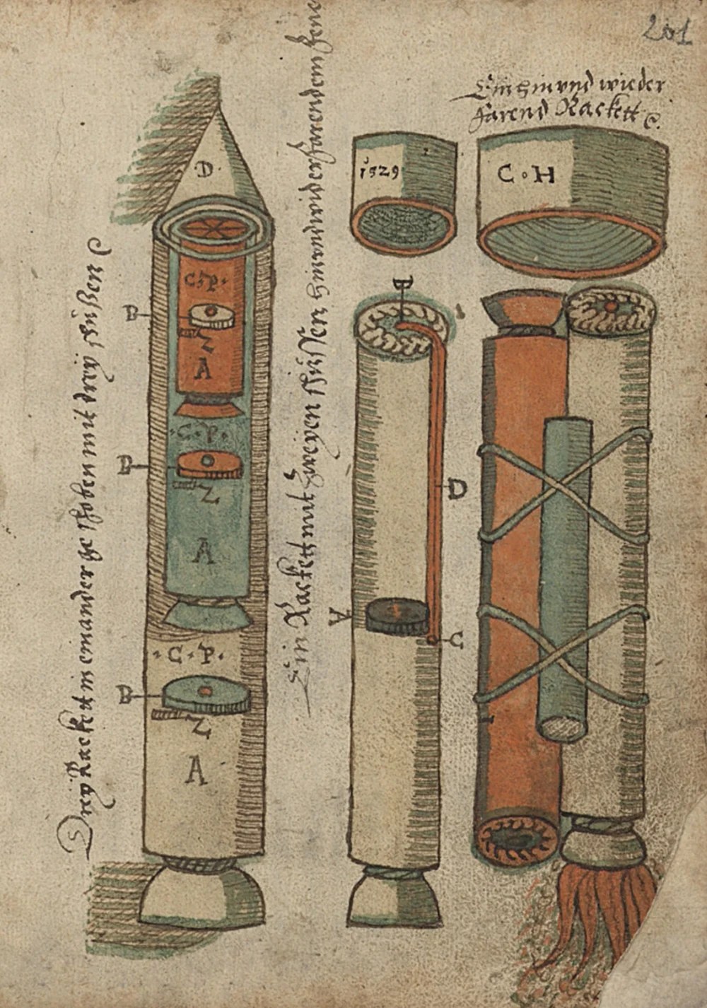
At the top of the leaf, on one of the separately drawn components, you can see 1529 and the initials C H. These are concrete marks on the page. They must be read alongside the rest of the book, where the dates do not follow chronological order.
The Bavarian Academy catalogue notes late dates on drawings near the beginning of Haas’s section and earlier dates further on. They may refer to designs or preliminary drawings. A dated leaf does not make the whole volume a continuously written diary.
Handschriftencensus uses 1529–1569; KdiH records drawing dates through 1568. KdiH ↗ · Handschriftencensus ↗
Three bodies in one cutaway
One rocket inside another. And another. ↗
In the left-hand drawing, the outer body encloses the green one, which encloses the red one. Their flared mouths appear at different heights. The drawing reveals the exterior and internal arrangement at the same time.
Hans Barth transcribes Haas’s description as “Drey Rackett ineinander geschoben”: three rockets inserted into one another. The colours help the eye follow the parts. We have no original legend that turns them into codes for three different fuels.
The digital cutaway separates the bodies so that you can inspect their relationship. This opening for inspection is not a stage in a historical flight.
The three-stage drawing is figure 2 in Carafoli and Nita’s study, p. 5. Barth ↗ · Carafoli–Nita ↗
Material matters
The cover could be paper. ↗
A rocket in a sixteenth-century notebook should not automatically be imagined as a metal cylinder. Carafoli and Nita describe a treated paper cover that burned with the propellant. Their passage refers explicitly to the two-stage drawing.
For the three-stage drawing, they say the operation was similar. Paper is therefore an interpretation supported by their explanation, with that limit. The model’s fibres, thickness and irregularities are digitally constructed; the drawing does not measure them.
Carafoli and Nita, pp. 4–5. This model does not reproduce a surviving, measured historical object. Carafoli–Nita ↗
Look at the edge
A cover has thickness too. ↗
Move closer to the open edge. The model shows overlapping sheets, short fibres and a rim that is not perfectly regular. These details make a flexible paper material understandable, rather than presenting a smooth surface with no thickness.
In his discussion of rocket-making craft, Barth describes cases formed from several glued layers of paper. That passage does not establish how many sheets were used in this leaf’s rocket. The visible layer count, curvature and opening of the wall belong to the digital interpretation.
The original suggests thickness with outlines and hatching. Compare the model’s edge with the small detail from the drawing: that is where the direct visual evidence ends.
Barth, “Haas und seine Leistung”. Colours and hatching can be inspected in the original scan. Barth ↗ · Commons ↗
A repeated part
Discs with a central mark. ↗
A round component with a small central mark repeats in the drawn bodies. Hatching around its edge suggests thickness. The surrounding letters point to the manuscript’s explanations.
Here you can examine one close up, brought forward from the cutaway. The model preserves its general shape and central mark, without assigning a verified material or a mechanical function established by this project. We do not automatically call it a valve, injector or separation device.
That restraint matters: an old technical drawing can easily become too modern if every familiar-looking part receives the name of a present-day mechanism.
The shape and central mark are visible on fol. 201r; this reproduction does not establish whether the mark represents an opening. Their exact function is not established in this explanation. Commons ↗
A detail at the opening
There is a star inside. ↗
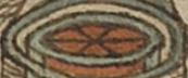
At the mouth of the inner body, the drawing shows a radially divided shape. Dark outlines meet at its centre. The model’s top view follows this detail, which is easy to miss when looking at the entire leaf.
Carafoli and Nita separately discuss a star-shaped charge in some manuscript rockets and compare it with the burning surface of modern solid propellants. That is their technical reading. This reproduction does not establish channel dimensions, a burn profile or a manufacturing recipe.
The geometric resemblance is enough to deserve a closer look. It is not enough to calculate this rocket’s performance.
Carafoli and Nita, p. 6; detail visible in the scan of fol. 201r. Carafoli–Nita ↗ · Commons ↗
At the end of each body
The mouths flare outwards. ↗
At the base of the large body, the shape narrows and then opens like a bell. A similar outline appears at the ends of the smaller bodies inside the cutaway.
Barth draws attention to these bell-shaped outlets. A present-day reader may immediately think of a modern rocket nozzle. The drawn shape alone, however, does not supply a measured profile, gas pressure or expansion efficiency.
The model shows a flared mouth following the page’s outline. Its internal surfaces and lip thickness are interpretive. In the equation you will use below, effective exhaust velocity will be an explicit assumption.
We do not identify this as a calculated, tested modern nozzle. Barth ↗ · NASA ↗
The same leaf, a different design
The bindings belong to the adjacent rocket. ↗
The right-hand drawing has a red element, a smaller tube and crossed green bindings. It also has its own inscription. These parts should not be transferred, for convenience, to the three-stage rocket on the left.
Barth identifies this as a rocket intended to travel out and return. In his reading, two chambers exhaust in opposite directions, with the second igniting for the return. That is an intention described by a historian, without a measured trajectory here.
The adjacent object is now a separate interpretation of this second drawing. Its bindings follow the visible crossings. The red element’s function remains unspecified; we do not present it as a proven ignition path for the three-stage rocket.
Barth, “Haas und seine Leistung”, discussion of fols. 201 and 205, figs. 18–19. Barth ↗ · Commons ↗
Choose a motor
One motor begins. The next carries on. ↗
Carafoli and Nita explain successive ignition through the two-stage drawing: the first motor sets the assembly in motion, then flame reaches the second motor’s propellant.
On the next page they describe the three-stage rocket’s operation as similar. Select the motors in turn to follow this reading. In a working object, the construction would determine the sequence; in this explanation, you choose when the view changes.
The flame is illustrative. It does not indicate a historical temperature, jet length or burn duration.
Carafoli and Nita, pp. 4–5. We have no recording here of the actual ignition sequence. Carafoli–Nita ↗
Scroll to consume the cover
What remains after the burn? ↗
Paper changes how the first stage should be imagined. In Carafoli and Nita’s explanation, the cover burned with the propellant. Once the first stage was exhausted, the next motor continued as an independent body.
Their passage concerns the two-stage rocket; extending it to three relies on their statement that it worked similarly. The disappearing cover is an illustration of that interpretation, controlled by scrolling.
Below, you will do something different: in a modern experiment, decide whether to release an empty casing that has remained intact. This isolates the problem of mass and does not claim to reconstruct Haas’s separation system.
Neither the disappearance rate nor the shape of the charred edge is a historical measurement. Carafoli–Nita ↗
Why does a rocket move?
Gas goes one way. The body goes the other. ↗
A rocket does not need to push against air to propel itself. It expels gas and changes its motion in the opposite direction. The arrows show those directions only; their lengths are not a scale of velocities or forces.
As propellant is consumed, the remaining mass changes. If a motor also has to accelerate empty covers, the same amount of propellant produces a different result from leaving those covers behind.
The ideal rocket equation expresses that relationship through a mass ratio and effective exhaust velocity. It is a modern explanation used here to understand the principle.
NASA Glenn, “Ideal Rocket Equation”. Effective exhaust velocity includes pressure’s contribution to thrust. NASA ↗
A drawing and a trial are different evidence
What was tested in 1555? ↗
In his 1969 article, Doru Todericiu argued that the principles of the three-stage rocket were tested in Sibiu in 1555. Carafoli and Nita mention successful experiments with the preceding, two-stage type, without dating them in that passage. These are not two confirmations of a single flight by the rocket drawn here.
Among the documents checked for this page, we have not identified a contemporary test log, an independent flight account or performance measurements. We cannot infer an altitude from them or claim that this digital model reproduces that flight.
Our failure to identify such evidence does not prove the trial never happened. It establishes the limit of this explanation: we can examine the drawing and historians’ readings, then test a physical principle separately.
Todericiu, 1969, pp. 475–479; Carafoli and Nita, p. 5. Image: two-stage drawing, figure 1, p. 4. Todericiu ↗ · Carafoli–Nita ↗
Your turn · a modern experiment
What is worth leaving behind? ↗
The rocket, fuel and payload stay the same. After each of the first two burns, decide whether to keep the empty casing. The next motor must accelerate everything you keep.
An ideal model, without air or gravity. It shows a change in velocity, not the altitude or performance of the historical rocket.
You decide what the next motor carries.
Drag the casing to the right or choose a button. Both choices use the same fuel.
The result of your choices
The fuel stayed the same: 6 kg. After a casing leaves, the gas pushes a smaller mass. That is where the extra velocity comes from.
Compare all four choices
| Casings left behind | Δv | Mass still on board |
|---|---|---|
| Neither | 347 m/s | 7.8 kg |
| First | 460 m/s | 4.5 kg |
| Second | 373 m/s | 5.6 kg |
| Both | 557 m/s | 2.3 kg |
Δv = vₑ ln(m₀ / m₁)
This example uses 6 kg of propellant, 6.6 kg of structure, a 1.2 kg payload and a specific impulse of 62 s. These are demonstration values. The final casing stays on board.